Welcome to LAIXL, producing EL testers, IV testers, and drone EL
uav-el

Product introduction The LX-H601 comprehensive insulation resistance tester is used for electrical safety testing of photovoltaic power plant systems and insulation t...
咨询电话:+86 177-0622-2370
Product introduction
The LX-H601 comprehensive insulation resistance tester is used for electrical safety testing of photovoltaic power plant systems and insulation testing of high-voltage power equipment. The whole machine covers voltage testing, continuity grounding testing, polarity testing, insulation testing, insulation fault location, etc.
The safety test of LX-H601 photovoltaic system can effectively detect the insulation performance degradation caused by long-term exposure to outdoor environment, which is susceptible to factors such as humidity and dust. Regular insulation resistance testing can promptly detect potential insulation faults, prevent safety accidents such as leakage and short circuits, and ensure the safe operation of the system.
The safety testing of LX-H601 photovoltaic system can accurately locate insulation fault points in the photovoltaic system, such as cable damage, junction box water leakage, etc. This helps maintenance personnel to quickly carry out repairs or replacements, reducing system downtime. The insulation resistance test result is one of the important indicators for evaluating the overall state of the photovoltaic system. By comparing test data from different time periods, the trend of insulation performance changes in the system can be analyzed, providing a basis for system maintenance and optimization.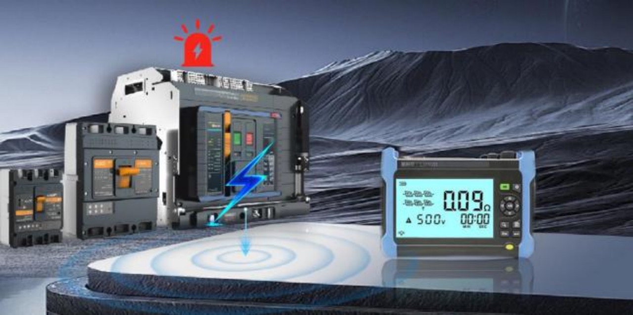
Detection advantages
National standard industry benchmark
The equipment complies with international and industry standards and can serve as a third-party measurement basis.
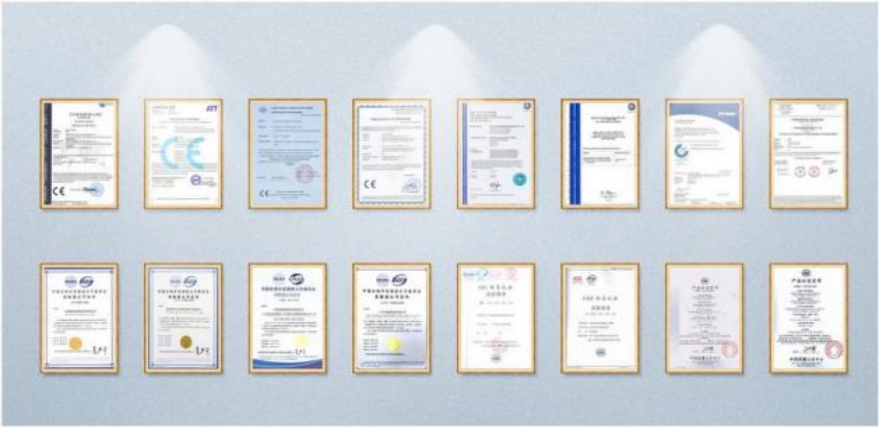
Compliance with standard specifications: According to the standard specifications of the photovoltaic industry, photovoltaic systems need to undergo regular insulation resistance testing to ensure that the insulation performance of the system meets relevant requirements. This helps to improve the reliability and durability of photovoltaic systems.
IEC 62852: 2014 "DC Application Connectors in Photovoltaic Systems - Safety Requirements and Testing"
GB/T 18380.3-2008 "Cables and Photovoltaic Cable Relays for Photovoltaic Power Stations Part 3: Cables and Ropes" GB/T 37364-2019 "Wires for Photovoltaic Modules"
GB/T 9535 "Acceptance Specification for Semiconductor Solar Cell Modules"
GB/T 9536 "Quality Inspection Method for Semiconductor Solar Cell Modules"
In practical applications, insulation resistance testing requires the use of a professional insulation resistance tester. Before testing, it is necessary to cut off the power supply of the tested photovoltaic system and ensure that the connection between the testing instrument and the tested system is correct and error free. During the testing process, attention should be paid to safe operation to prevent accidents such as electric shock. The test results should be recorded in detail and archived for future analysis and reference.
Test Scope
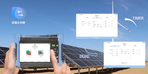
DUAL mode of insulation resistance: It is a specific testing mode commonly used to simultaneously detect the insulation resistance values of positive and negative poles to ground in circuits or equipment. It is an efficient and accurate insulation resistance testing mode with wide application value in multiple fields. By using DUAL mode for testing in a reasonable manner, potential insulation faults can be detected and addressed in a timely manner, ensuring the safe and stable operation of the electrical system.
TIMER mode of insulation resistance: a commonly used function in insulation resistance testing, which allows testers to set a specific testing time and automatically stop testing and display the insulation resistance value after reaching that time. This mode is particularly suitable for scenarios that require long-term stable testing or batch testing, and can significantly improve testing efficiency and accuracy of results.
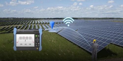
GFL mode for insulation resistance fault location: Used for detecting and locating insulation faults to ground in electrical systems. It mainly monitors and diagnoses the location of insulation faults in real time by measuring the insulation resistance between the phase conductor of the electrical system and the ground. Used for insulation performance testing of photovoltaic modules, photovoltaic strings, or the entire photovoltaic array, it can locate insulation faults caused by water or moisture infiltration.
RPE mode for protecting conductor continuity: The grounding continuity resistance of the protective conductor is used to measure the resistance value of the grounding part connected to the grounding point through the grounding conductor in the safety grounding system of electrical equipment. It is an important item in electrical safety testing, mainly used to detect whether the grounding system of electrical equipment can work effectively under fault conditions. The purpose of the test is to ensure that the protective grounding of electrical products can effectively and reliably conduct dangerous voltages to the ground after basic insulation failure, preventing harm to human health.
Polarity testing (PI): Evaluating the health status of electrical equipment insulation systems, reflecting the dryness, contamination level, and potential insulation defects of insulation materials.
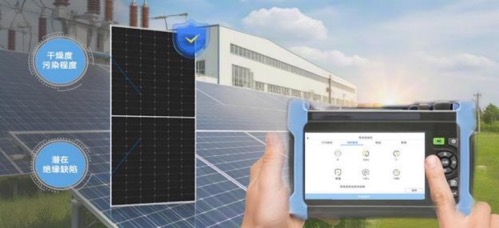
Features and advantage
1500V/40A double-sided component testing
H601 can be tested on single-sided and double-sided modules up to 1500V/40A, and can adapt to various high-voltage and high-power photovoltaic module testing scenarios. H601 not only has a large measuring range, but also intelligently determines test results. Provided fast component/string performance testing and DC side efficiency analysis testing functions for photovoltaic power plant testing.
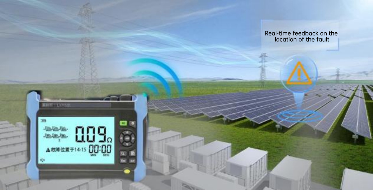
GFL function locates the location of insulation faults in the string
By using an inverter or a matching intelligent photovoltaic app, alarm information can be obtained to preliminarily determine whether there is an insulation fault. And it can help determine the specific location of the suspected fault in the photovoltaic string. By disconnecting and connecting suspected faulty photovoltaic modules or optimizers, the fault location can be further verified. If the alarm disappears after disconnecting a certain part, it indicates that the fault is in that part.
Specifications
| Specification parameters | ||
| Category | Value | LX-H601 |
| DC voltage test | Measuring range | 3~1500V |
| Measure reading | 1V | |
| Test accuracy | ±1%rdg±2V | |
| AC voltage test | Measuring range | 3~1000V |
| Measure reading | 1V | |
| Test accuracy | ±1%rdg±3V | |
| Insulation resistance measurement (DUAL to ground) | Voltage measurement range DC (V) | 250;500;1000;1500 |
| Resistance measurement range (M Ω) | 0.1~0.99(0.01) ;1.0~19.9(0. 1);20~100(1) | |
| Resistance measurement accuracy | ±5%rdg±5Ω | |
| Insulation resistance measurement (timed TIMER) | Voltage measurement range DC (V) | 250;500;1000;1500 |
| Resistance measurement range (M Ω) | 0..1~9.99 (0.01);10~100(0. 1) | |
| Resistance measurement accuracy | ±5%rdg±5Ω | |
| Ground Fault Localization (GFL) | Functional Description of Photovoltaic Applications* | Locate the ground insulation fault point, that is, the position of the faulty component in the photovoltaic string |
| Application Function Description of High Voltage Power Equipment | Insulation testing of high-voltage equipment such as cables, transformers, and switchgear to ensure the stability of the power system | |
| Function Description of Electric Vehicle Applications | Monitor the insulation resistance of the positive and negative busbars of the high-voltage direct current system to ground, as well as the insulation of the battery pack and the entire machine | |
| Real-time Monitoring | Continuous monitoring system for insulation resistance status during charging or allowing process | |
| Accurate positioning | When the insulation resistance is lower than the preset value, an alarm signal is issued and the location of the fault is indicated | |
| DC voltage test | 250;500;1000;1500 | |
| DC Resistance Test | 0.1~0.99(0.01) ;1.0~19.9(0. 1);20~100(1) | |
| Continuity test of protective conductor (RPE 200mA) | Resistance test range (Ω) | 0.00~9.99(0.01) ;10.0~100(0. 1);100~1999(1) |
| Resistance measurement accuracy | ±2%rdg±2Ω | |
| Equipment functional testing | Test Current | 200mA protective conductor continuity test |
| Testing voltage | 250 、500 、1000 、1500 VDC | |
| Measure DC voltage | 1500V | |
| Measure the AC TRMS voltage | 1000V | |
| Insulation test | DUAL and TIMER | |
| Insulation fault location | GFL | |
| Polarity Tes | PI | |
| Absorption ratio at the intermediate point | DAR | |
| Determination of measurement results | Normal/Abnormal | |
| Display content for direct testing | Immediately display the DC and AC effective voltage between the positive and negative poles and the grounding electrode, and immediately display the RPE value and determine OK/NO | |
| Hardware parameters | ||
| Category | Value | LX-H601 |
| Standard configuration | Host | Test Host |
| Test Line | 4-color testing line+4-color crocodile clip | |
| Adaptive line | 2-color MC4 adapter connector | |
| Software | Chinese Windows software+USB cable | |
| Portable package | Bag+shoulder strap | |
| External battery charger | Standard configuration | |
| Portable case | Hard plastic portable case | |
| Calibration reports | Historical Calibration Report | |
| User's manual | Chinese User Manual | |
| Test Line | 2 extension cables banana plugs 20m | |
Instructions for using other functions:
1. Quickly detect and verify the insulation resistance (OK | NO) of the active conductors in the components, strings, and photovoltaic arrays of the photovoltaic system, without the need for external switches to test short circuits on the positive and negative terminals.
2. Automatically identify the overall insulation compliance of the entire photovoltaic array through a single test to meet regulatory (standard) requirements. can
Simultaneously indicate the insulation resistance values of the positive and negative electrodes to ground, giving the operator the opportunity to conduct testing and research on the actual location of the fault.
3. Immediately test and verify (OK | N O) by calculating the dielectric absorption ratio (DAR=R1min/R30s) and polarization index (PI=R10min/R1min) to calculate the insulation resistance of the cable, thereby verifying the degradation state of the insulator.
4. Provide the exact location of individual faults that may cause insulation failure in photovoltaic system strings
5. Immediately verify (OK | NO) the continuity of the protective conductor and its output test current will be>200mA
6. Immediately display the effective DC and AC voltages (including any AC components) between the positive and negative poles and the grounding electrode.

2024.12.30

2024.12.28
 +86 177-0622-2370
Address: 4409 Wuzhong Avenue, Suzhou City, Jiangsu Province
Phone: +86 17706222370
Email: el@lailx.com

LINE